1. Introduction to Connector Parameters:
In the connector industry, terms like "top mount" and "middle mount" are relatively easy to understand. However, when it comes to more technical specifications like "offset" and "CH", confusion can arise. These parameters are crucial in connector design, especially for SMD (Surface Mount Devices), which are commonly used in various electronic devices.
This blog will explain the definitions of Offset and CH, their similarities and differences, and offer insights into how they affect connector design.
2. What is "Offset" in the Connector Industry?
The term "offset" refers to the displacement or deviation of the connector's mounting points in relation to the PCB (Printed Circuit Board) or the connector itself. It is often expressed in millimeters (mm) and is a key consideration for ensuring proper alignment during assembly. In the context of Surface Mount Technology (SMT), an offset can determine how the connector is positioned on the PCB, affecting the overall fit and function of the connector.
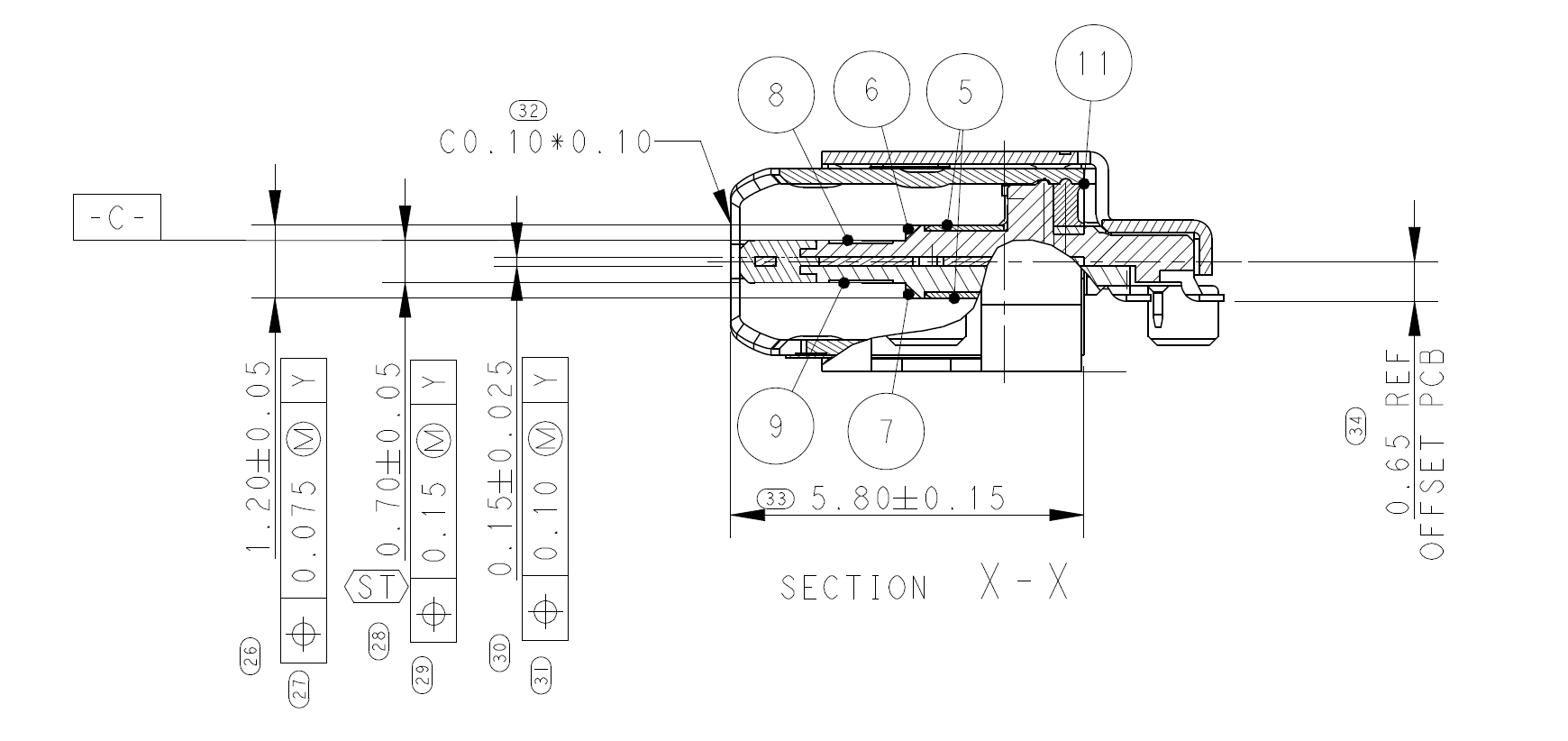
In the case of TE Connectivity connectors, "Offset" typically refers to the vertical distance between the mounting points of the connector relative to the board. For instance, an offset of 0.65mm means that the connector’s mounting hole is shifted by 0.65mm relative to the PCB.
The drawing data is sourced from TE, and all copyrights belong to TE.
图纸数据来源于 TE,相关版权归 TE 所有。
3. What is "CH" in Connector Terminology?
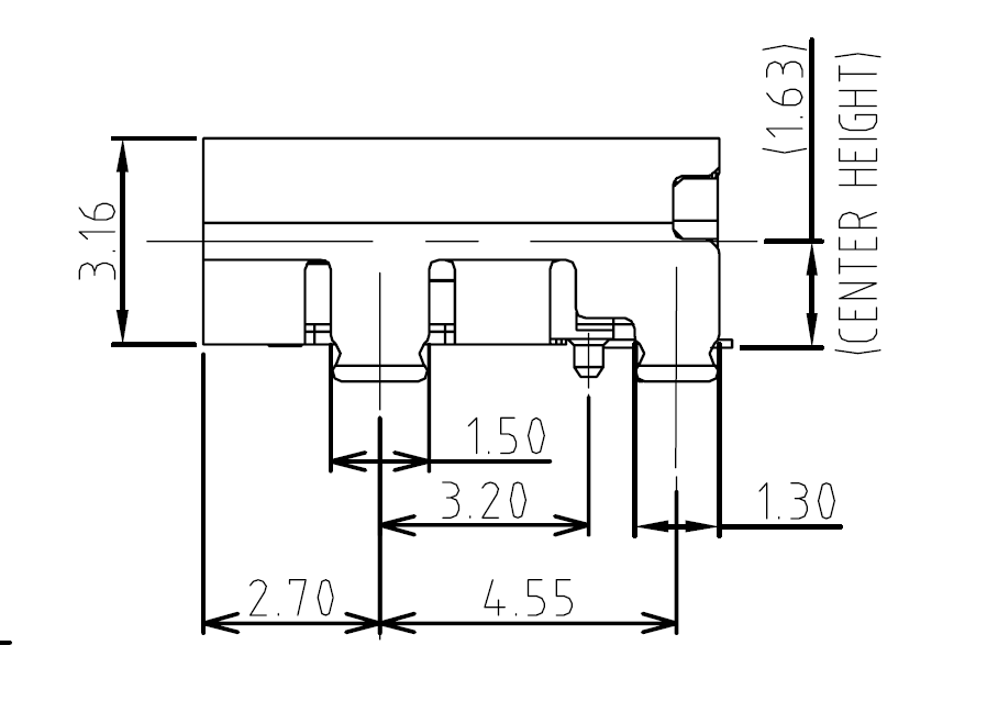
CH, short for "Center Height", defines the height of the connector’s center relative to the PCB’s surface. It is another critical dimension in connector design because it influences how the connector interacts with other components on the board. Similar to the offset, CH is measured in millimeters and can affect the connector’s mechanical stability, electrical performance, and ease of assembly.
While offset refers to the horizontal or vertical shift of the connector, CH specifically measures the height at the center point.
4. Comparing Offset and CH:
The following table summarizes the key differences between Offset and CH:
|
Parameter
|
Offset
|
CH (Center Height)
|
|
Definition
|
Horizontal or vertical displacement of the connector relative to the PCB
|
Height of the connector’s center point relative to the PCB surface
|
|
Impact on Design
|
Affects the overall positioning and alignment during assembly
|
Affects the mechanical and electrical stability of the connector
|
|
Measurement
|
Measured in millimeters, typically as a shift in the connector’s position
|
Measured in millimeters as the center height of the connector
|
|
Purpose
|
Ensures proper fit and alignment with the PCB
|
Ensures correct clearance and interaction with other components
|
5. Visualizing with TE Connectivity Drawings:
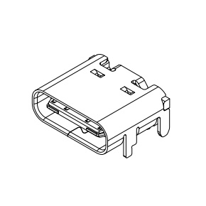
To understand these terms better, we can refer to the official TE Connectivity connector drawings. For example, the diagram from TE's USB C receptacle drawing (page 2 of the file) shows the offset dimension of 0.65mm, which indicates the connector's relative position to the PCB. The drawing also provides clear annotations of the mounting points and their relationship to the PCB, helping to clarify the concept of offset.
Similarly, CH would be illustrated in a detailed technical drawing where the center height is defined relative to the PCB surface.
6. Conclusion:
Both Offset and CH are crucial parameters in connector design, and understanding their differences is key to selecting the correct components for your application. If you have further questions or need clarification on these terms, feel free to contact us for a more in-depth discussion.
 English
 中文
中文